

What Is Electronic Distance Meter

What is EDM in Surveying?
This EDM deals with the principles and procedures of separate Electronic distance measuring device (EDM) instruments that are mountable with optic/electronic theodolites.
Original EDMs were individual units used but for altitude measurements.EDM instruments used as modular components in modern total stations likewise work under the aforementioned principle of separate EDM instruments.
EDM was offset introduced in the 1950s and has undergone several modifications.
- The early on versions of the instruments, though very precise over long distances, were very large, heavy, complicated, and expensive.
Electronic theodolite/optic theodolite mountable EDM was introduced first, and these are being used nonetheless today. Rapid advances at related technologies have provided lighter, simpler, and less expensive instruments.
The latest versions of EDM instruments are used as a modular component of total stations. Some earlier versions of EDM instruments used natural low-cal for the calculation of distances, but the latest version of EDM uses infrared light, laser light or microwaves.
Also, read: Methods of Design | Difference Between Working Stress Method and Limit State Method
Types of EDM Instruments
Depending on the types of carrier moving ridge employed, EDM instruments can exist classified nether the post-obit three heads :
- Infrared Instruments.
- Microwave Instruments.
- Visible Light Instruments.
For the corresponding frequencies of carrier waves, the reader may refer back to every bit per fig no-5. It is seen that all the to a higher place three categories of EDM instruments utilise short wavelengths and hence, higher frequencies.
ane. Infrared Instruments.
Infra-ruby radiations (IR) classifies these instruments almost commonly utilized in applied science. The IR has wavelengths of 0.viii-0.ix pm transmitted by gallium arsenide (GaAs) luminescent diodes, in a high, continuous frequency.
The accuracies needed in altitude measurement are those that the measuring moving ridge can't exist used directly because of the poor propagation characteristics.
The measuring wave is consequently superimposed on the high-frequency waves created, chosen carrier waves. The superimposition is achieved by amplitude (as per below fig-5), frequency (equally per below fig-vi), or impulse modulation (as per beneath fig-seven).
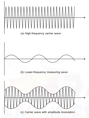
Carrier moving ridge modulation Fig no -v
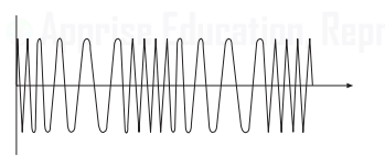
Frequency modulation of the carrier moving ridge Fig no- 6
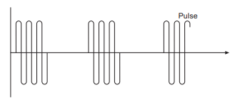
Impulse modulation of the carrier wave Fig no -seven
In the case of IR instruments, amplitude modulation is utilized. Hence the carrier wave develops the necessary measuring characteristics whilst keeping the high-frequency propagation characteristics, which could exist measured with the necessary accuracy.
Lots of the tools using visual low-cal waves have a greater range and a far greater accurateness than that required for more general surveying piece of work.
Lots of the tools using visual light waves have a greater range and a far greater accuracy than that demanded for more general surveying work.
Typical of these tools are the KernMekometer ME 5000, authentic to ±0.two mm ±0.ii mm/km, with a range of eight km, also as the Com-Rad Geomensor CR234.
Also, read: Deviation Betwixt One Way Slab and Two Way Slab | What is Slab
2. Microwave instruments
Microwave tools utilize radio wavelengths as carriers and for that reason, need two instruments, one at the end of this line to be quantified, which are capable of receiving and transmitting the signals.
The microwave carrier is e'er frequency modulated (as per below fig-6) for measuring purposes and has wavelengths usually in the club of 10 cm and 3 cm.
As these instruments don't rely on the light being returned into the main instrument by a reflector, they may be used nighttime or twenty-four hour period in most weather conditions. These instruments are capable of long ranges around 25 km and beyond, with typical accuracies of ±x mm ±5 mm/km.
3. Visible Lite Instruments.
The final classification of equipment refers to those tools which utilize long radio waves with wavelengths of 150 thousand to 2 km.
They're primarily used for position-fixing systems in hydrographic and oceanographic surveying.
Typical examples would be the Pulse 8 organisation as well equally also the Syledis organization, for offshore position fixing.
The in a higher place nomenclature shows that it would also be possible to classify by range, for example
- Curt-range, electro-optical instruments using amplitude-modulated infra-red or visible light with ranges up to five km.
- Medium-range microwave equipment, frequency modulated to give ranges around 25 km.
- Long-range radio moving ridge equipment with ranges upwards to 100 km.
As well, read: What Is Cement | Types of Cement
Measurement Principle of EDM Instrument.
The principle of the measurement device in EDM, which is currently used in a full station and used along with electronic/optic theodolites, is that it calculates the distance past measuring the phase shift during the radiated electromagnetic moving ridge (such as infrared light or laser lite or microwave) from the EDM'south master unit, which returns past being reflected through the reflector, which is positioned at a measurement point (as per beneath figure no-1).
This phase change tin be regarded as a function of the frequency, which appears as the unit of measurement of length or fourth dimension nether a specific status.
After the gradient distance L along with the slope angle Ø are measured past EDM, if the elevation of point A is the reference bespeak, nosotros could discover the peak of point B from the following formula (According to below figure no-2)
- Superlative Point B = Height of Bespeak A + Hi ± L sin Ø — HR ————- (Eqn. 1)
EMDs Construction Fig No.-1
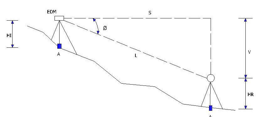
Slope Altitude (Horizontal Distance Mistake) by incidence angle Fig No.-two
As per figure no-iv, shows a wave of wavelength λ. The wave is traveling along the X axis with a velocity of 299,792,560.4 km/sec (approximate velocity of light in vacuum).
The frequency of This wave is That the time is taken for ane complete wavelength.
- λ = c/f
- λ = Wavelength in meters
- c = velocity in km/sec.
- f = frequency hertz (one wheel per second)
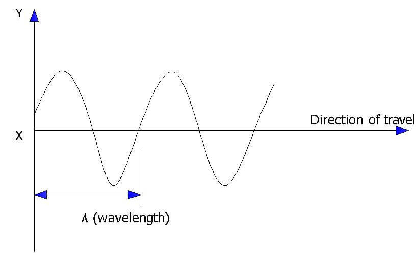
EDM Wave Fig No – 3
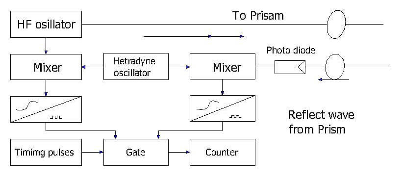
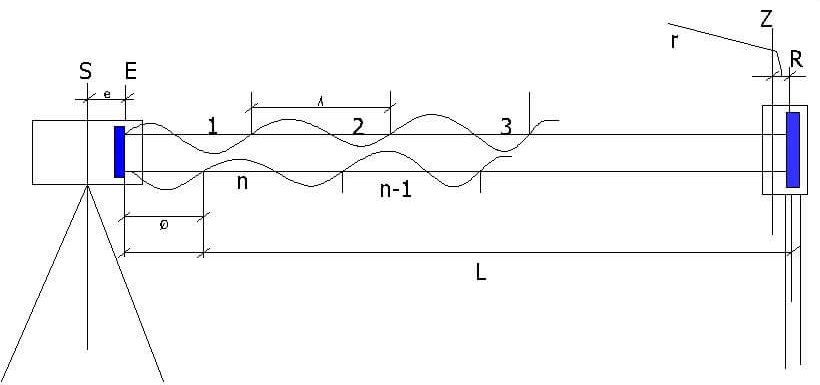
Every bit per fig, No-iii shows a modulated electromagnetic wave being emitted from an EDM instrument and being reflected and existence reflected back to the musical instrument.
Here the double distance is taken as 2L, which is equal to the full whole number of wavelength nλ and the particle wavelength w.
Therefore, the distance between the EDM instrument and the reflector (50) is calculated as follows:
- 50 = (nλ + φ ) / iiMeters
The partial wavelength (westward) is determined by calculating the phase shift required and reflected waves, that is, by calculating the phase delay required to friction match precisely the transmitted and the reflected waves.
- S = Station
- r = Reflector component of add-on abiding
- Z= Target
- E = References aeroplane within the EDM for phase comparison
- λ = Modulation of wavelength
- W = Fraction to be measured of a whole wavelength of modulation Δλ
- eastward = Altitude meter component of improver constant
- R = Reference plane the reflection of the wave transmitted by the EDM
The musical instrument transmits a series of three or iv modulated waves at dissimilar frequencies.
By substituting the resulting values of λ and westward in the above equation for three or 4 different frequencies, the value of northward can be constitute.
The Tools Were Created to carry out That process within seconds and brandish the value of L.
Some EDM instruments utilise pulsed laser emissions, and these instruments decide the distance by measuring the time taken between the transmission of this sign and the reception of the reflected signal, by taking advantage of the pulsed light amplification by stimulated emission of radiation axle.
The velocity of low-cal (electromagnetic waves) through the temper can be afflicted by:
- Temperature
- Atmospheric pressure
- Water vapor content in the atmosphere
The corrections for temperature and pressure are adamant manually by referring the monograms given with all total stations (as per below fig-4), or the corrections are calculated automatically in the instrument itself by inputting the values for temperature and pressure level.
Principle of Electronic Distance Measurement Fig No.-four
For measuring short distances using EDM instruments, atmospheric corrections are relatively insignificant. For measuring long distances, atmospheric corrections become quite of import.
As well, read: What Is a Bar Bending Schedule | Preparation every bit Per Bs 4466 | Tolerances as Per Bs 4466
Errors in Electronic Distance Measurement
Types of Error
- Personal Errors
- Instrumental Errors
- Natural Errors
#i Personal Errors
Personal errors include with inaccurate setups of EDM instruments and reflectors over stations, faulty measurements of reflector and instrument heights [Required for computing horizontal lengths ], and errors in determining atmospheric pressures and temperatures. These errors are largely random.
They can exist minimized by exercising the utmost care and past using practiced-quality barometers and thermometers.
Mistakes (not errors) in manually recording and reading displayed distances are common and costly. They may be eliminated with a few instruments by obtaining the readings from both meters and feet too as comparison them. Of form, information collectors as well circumvent this problem. Additionally, as shown in table no-1, The misalignment of the prism may cause significant errors once the reflector is put in its 0 mm abiding position.
| Misalignment in Degrees | 0 mm Abiding Prism Error (mm) | −xxx mm Constant Prism Error (mm) |
| 0 | 0.0 | 0.0 |
| v | 0.1 | 0.0 |
| 10 | 0.6 | 0.1 |
| 15 | i.3 | 0.ii |
| 20 | 2.3 | 0.4 |
| 25 | three.5 | 0.7 |
| 30 | 5.1 | 1.1 |
Error in Observed Altitude considering of Misalignment of the Prism Table no-1
Example of a common error is failing to set the temperature and pressure in an EDM prior to receiving an ascertainment.
Assume this occurred using the atmospheric atmospheric condition given in the accurate index of refraction was calculated as 1.0002672. IIf the fundamental wavelength for a standard atmosphere was 10.000 m, Then then the real wavelength produced by the EDM will be x.000\one.0002672 = 9.9972m.
Using Equation V = f . λ Having an observed distance of 827.329 m, the error, e, at the observed altitude could be
e = [( 9.9973 – 10.000)/ x.000] x 827.329
due east = -0.223 m
The effect of Neglecting to account for the atmospheric conditions produces a precision of Simply|-0.223 |/827.329 or 1:3700.
This is well under the computed precision of one:195,000
For each 1°C change in temperature, a i ppm mistake in the distance measurement will occur. As a rule, the current temperature and pressure should exist set up at the fourth dimension of the measurement.
However, it is often practical to gear up the temperature and force per unit area three or four times per twenty-four hours: morn, midmorning, apex, and midafternoon.
At a minimum, the temperature and pressure should be set twice a day; in one case in the morn and at noon. However, a lower-accuracy survey will issue. Table no-2 depicts the altitude fault in millimeters versus the error in temperature entered into an EDM for various lengths of sight.
| Error in Temperature | Length of Sights (m) | |||||
| °C | °F | 100 | 200 | 300 | 400 | 500 |
| 3 | five.4 | 0.3 | 0.6 | 0.9 | 1.2 | 1.5 |
| six | ten.8 | 0.6 | 1.ii | 1.eight | 2.4 | 3 |
| nine | 16.two | 0.ix | ane.eight | 2.7 | iii.6 | four.5 |
| 12 | 21.half-dozen | 1.ii | two.4 | 3.6 | 4.8 | 6 |
| 15 | 27 | 1.v | 3 | 4.five | 6 | 7.5 |
| 30 | 54 | 3 | 6 | nine | 12 | xv |
Tabular array No-ii, Error in Observed Distance in Millimeters versus Mistake in Temperature for Diverse Sight Lengths
Find that an error of i mm tin can occur for all distances over 50 g when the temperature mistake is more than than nine°C. This temperature deviation can hands occur during certain times of the year between early morning, midday, and late afternoon.
Likewise, annotation that this mistake will occur with just a 3°C temperature error for sight lengths that are greater than 300 m.
Likewise, read: Lab Test on Aggregates at Site
#2 Instrumental Errors
In the instance of EDM equipment is advisedly adjusted and precisely calibrated, instrumental errors ought to exist exceedingly small
To ensure their accuracy and reliability, EDM instruments should be checked confronting a first-club baseline at regular time intervals.
For this purpose, the National Geodetic Survey (NGS) has established a number of accurate baselines in each state.
All these are approximately a mile in length and placed in relatively flat areas. Monuments are put in the ends and at intermediate points along the baseline
Though most EDM instruments are quite stable, sometimes, they get maladjusted and create erroneous frequencies.
This results in faulty wavelengths that hamper infinite measurements. Periodic checking of this equipment confronting a calibrated baseline will Discover the existence of observational errors. It's specially of import to make these checks if high-society surveys take been conducted.
The corner cube reflectors used for EDM instruments are just another source of instrumental error. Since lite travels in a lower velocity in glass than in air, the"effective center" of this reflector is really behind the prism.
Therefore, it oftentimes doesn't coincide with the plummet, a condition that produces a systematic fault in distances referred to equally the reflector constant.
This situation is shown every bit per below fig five. Notice that since the retroreflector is comprised of mutually perpendicular faces, the light travels a full distance of a + b + c = 2D from the prism.
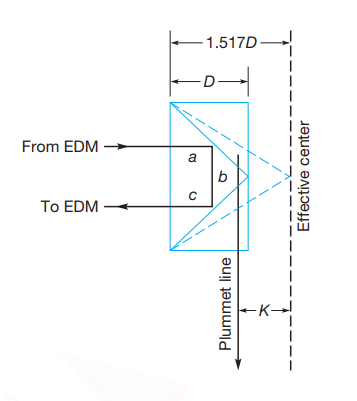
Schematic of retroreflector in that location D is the depth the prism fig no. -5
Additionally, given as a refractive index for glass, which is greater than air, the velocity of calorie-free in the prism is reduced this Equation V = c/n to create an constructive distance of nD where northward is the index refraction of the glass.
The dashed line in as per to a higher place fig no 5 shows the constructive centre thus created. The reflector abiding, Grand in the fig., tin be every bit large equally 70 mm and will vary with reflectors.
Once known, this electric heart of the EDM can exist shifted forward to compensate for the reflector abiding.
However, when an EDM instrument is being used regularly with several unmatched reflectors, this shift is impractical. In this case, this offset for each reflector should be subtracted from the observed distances to obtain corrected values.
With EDM instruments that are elements of total stations and are controlled by microprocessors, this constant tin can exist entered through the keyboard and included in the internally computed corrections.
Equipment manufacturers too create matching reflector sets for that the reflector abiding is the same, thus allowing a single constant for use to get a set of reflectors with an instrument.
By assessing precisely known baseline lengths to observed distances, a then-called organization measurement abiding could be set.
This abiding tin then be applied to all subsequent observations for proper correction. Although calibration by ways of a baseline is favored, if ane is not available, the constant can be obtained with the following procedure.
Three stations, A, B, and C, ought to be established in a straight line on flat ground, with stations A and C in a distance that is multiple units of the cardinal wavelength of the instrument apart.
The central wavelength from near instruments today is typically ten k. Station B should be at betwixt stations A and C, also at a multiple of the fundamental wavelength of the EDM. For example, the lengths AB and BC might be prepare at 40 m and 60 thou, respectively, for an instrument with an as fundamental wavelength of ten k.
The length of Air-conditioning, besides as the two components, AB and BC, ought to be observed several times together with the instrument-reflector abiding set to zero and too the mode of each length determined. From these observations, the following equation could exist written:
Air conditioning + K = (AB + K ) + (BC + K)
for which Thou = AC – (AB + BC)
where K = the system measurement constant to be added to right the observed distances
The procedure, including the centering of the EDM instrument and reflector, should exist repeated several times very carefully, and the average value of that K adopted.
Since different reflectors take varying offsets, this test should be performed with any reflector that will exist used with the EDM, and this results marked on each to avoid confusion afterwards.
For the near precise calibration, this length AB and BC should be carefully laid out as fifty-fifty multiples of the instrument's shortest measurement of wavelength.
Failure to do this tin because an incorrect value of Chiliad to exist obtained. As shown as per above fig no v, due to the construction of the reflector and the pole being located virtually this center of the reflector, the system measurement constant is typically negative.
The video EDM-Reflector Offset Constant Conclusion, which is bachelor on the companion website for this volume, discusses this method.
While the above procedure provides a method for determining a specific instrument-reflector abiding, it is highly recommended that EDM instruments be calibrate using NGS scale baselines.
These baselines are established throughout the state to be used past surveyors. Their technical manual Utilization of Calibration Base Lines, that can be listed in the bibliography at the stop of this chapter, provides guidelines on using the baselines and reduction in the observations providing the instrument-reflector offset constant and a scaling cistron.
Also, read: Total Station in Surveying | Operations | Reward & Disadvantage | Types
#3 Natural Errors
Natural mistakes in EDM surgeries stem chiefly from atmospheric variations in pressure, temperature, and humidity, which touch on the alphabetize of modifying and refraction the wavelength of electromagnetic energy.
The values of the variables take to be measured and used to correct observed distances. As demonstrated in humidity can generally be neglected when using electro-optical instruments, but this variable was important when microwave instruments were employed.
The National Weather condition Service of adjusts atmospheric pressure readings to sea-level values.
Since atmospheric pressure changes by approximately one of mercury (Hg) per 1000 feet of altitude, under no weather ought to radio broadcast values for atmospheric pressure level exist utilized to set up distances.
Instead, atmospheric force per unit area should exist measured past an aneroid barometer that is calibrated against a barometer not corrected to sea level.
Many college and high school and physics departments have these barometers. EDM instruments with total stations take onboard microprocessors that use atmospheric variables, input through the keyboard, to compute corrected distances subsequently making observations before displaying them.
For older instruments, varying this transmission frequency fabricated corrections, or they could be computed manually afterwards the observation.
Equipment manufacturers provided charts and tables that assisted in this process. The magnitude of fault in EDM due to errors in observing atmospheric pressure level and temperature is indicated as per below fig No-6. Note a 10°C temperature mistake, or a pressure level difference of 25 mm (1 in.) of mercury, each produces a distance fault of most 10 ppm.
Thus in case, a radio circulate atmospheric pressure is entered into an EDM in Denver, Colorado, the resulting Distance error might be as good as 50 ppm, and a 200-m altitude could in error by upwardly to1 cm.
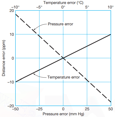
Errors in EDM produced by pressure or temperature errors. Fig No-6
A microclimate tin can exist at the layers of the temper immediately above a surface like the basis. Field experiments show that temperatures on or close to the ground mayhap 10° into 25° college or lower than those at shoulder height.
Since this microclimate can essentially modify this alphabetize of refraction, it's important to maintain a line of sight that'south at least 0.five m above the surface of the footing.
On long lines of sight, the observer ought to be cognizant of intervening ridges or other items that can exist between the instrument and reflector, which might lead to problems in meeting this condition.
If this condition can't be met, the height of the reflector might be increased. Under certain weather condition, it could exist required to set an intermediate point on the encroaching surface to ensure calorie-free in the EDM doesn't travel through those lower layers.
For the most precise piece of work, long lines, a sampling of those atmospheric weather condition forth the line of sight ought to exist observed.
In this example, it may exist required to elevate the meteorological instruments. This may exist difficult where the terrain gets considerably lower than the sightline. In such cases, the atmospheric measurements for the ends of this line could be measured and averaged.
FAQ
EDM in Surveying
Electronic distance measurement (EDM) is a method of determining the length between two points using electromagnetic waves. EDM instruments are highly reliable and convenient pieces of surveying equipment and can be used to measure distances of upwardly to 100 kilometers.
Electronic Distance Measuring Instrument
Electronic distance measurement (EDM) is a method of determining the length betwixt two points usingelectromagnetic waves.EDM is commonly carried out with digital instruments calledtheodolites.
What is Electronic Distance Measuring (EDM)?
AnElectronic Distance Measurer (EDM) can be used to identify objects or points in three dimensions in relation to the unit. The EDM emits a beam of infrared light that is modulated at a controlled rate. Additionally, the EDM also measures the azimuth, or bending from n, and elevation of a point.
What Are the Types of EDM Instruments?
- Microwave Instruments — Too chosen tellurometers, these instruments apply microwaves. And they have been around since the 1950's.
- Infrared Moving ridge Instruments — Uses prism reflectors that pick up amplitude modulated infrared waves at the terminate of a line.
- Visible Light Wave Instruments — Uses modulated low-cal waves to measure up to a specific range.
Principle of EDM (Electronic Distance Measuring)
Electronic altitude measurement (EDM) is a method ofdetermining the length between 2 points, using stage changes, that occur aselectromagnetic energy waves travels from i end of the line to the other end.
What Is EDM in Surveying?
Electronic distance measurement (EDM) is a method of determining the length between 2 points using electromagnetic waves.EDM instruments are highly reliable and convenient pieces ofsurveying equipment and tin can exist used to measure distances of upwards to 100 kilometers.

What Is Electronic Distance Meter,
Source: https://civiljungle.com/edm-in-surveying/
Posted by: banksobling.blogspot.com
0 Response to "What Is Electronic Distance Meter"
Post a Comment